RCX/NXT Geiger Counter (Ongoing)

Discussion specific to projects ideas and support.
circuitmage
Posts: 68
Joined: 14 Dec 2012, 17:56
Location: Austin, TX

RCX/NXT Geiger Counter (Ongoing)

Post by circuitmage »

I picked up a kit from Electronics Goldmine, they have one for less than $30 now. It works fairly well;

Tried using the LED and light sensor with an RCX, slightly problematic. Using the NXT and the sound sensor, works much better. Also, more sample space with the NXT for long runs.

http://www.youtube.com/watch?v=lz_XZMQVYMI

The only thing left is to make a good 9V supply to plug it into. I had one I thought would work, but it was not robust enough, or had some other issue. So, using bench PS ran it all night to collect data. Hoping to see slight variation in day/night counts. :)

After the fact, I've seen many other similar implementations on the web.

Edit:
Here is a link to the actual circuit ;
http://www.eetimes.com/design/programma ... nter-count#

Here is a Labview vi that collects CPM based on sound sensor "ticks" . Note: environment has to be quiet while collecting data. This is a simple indirect way of collecting data, but not as good as a wired connection...still thinking about that...
Attachments
NXT GC.zip
(32.05 KiB) Downloaded 744 times
Last edited by circuitmage on 25 Jul 2013, 17:32, edited 3 times in total.
circuitmage
Posts: 68
Joined: 14 Dec 2012, 17:56
Location: Austin, TX

Re: NXT Geiger Counter

Post by circuitmage »

Update:

Found a good 9V DC supply.

Looking at the LV DC sections on the scope, this circuit is very noisy. Since the HV Geiger Tube is AC coupled to the speaker and the LED, and the HV is not filtered (per eetimes article above), I had a hard time finding a way to capture the "ticks". Then I thought I'd try an optocoupler in place of the LED, and it worked!

Still hoping to interface this with an RCX or NXT. Waiting for some better optocouplers to get here this week.

Also, the GT hit events look like they are about 100us. So, that may be another issue.

Otherwise, I hope to have a portable Lego Geiger counter with datalogging done soon!
circuitmage
Posts: 68
Joined: 14 Dec 2012, 17:56
Location: Austin, TX

Re: NXT Geiger Counter

Post by circuitmage »

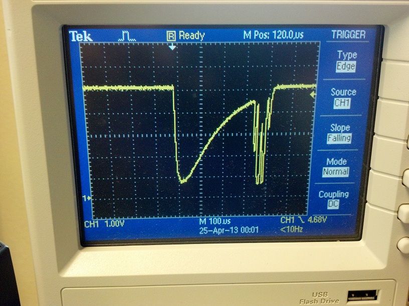
Looks like I may need some signal conditioning to get the RCX or NXT to capture these 100us pulses.

Any ideas on good ways to do this? Was hoping for a passive interface, as optos dont need power, signal is cleaned up significantly, but still too fast for poor RCX...


Image

Image
mattallen37
Posts: 1818
Joined: 02 Oct 2010, 02:19
Location: Michigan USA
Contact:

Re: NXT Geiger Counter

Post by mattallen37 »

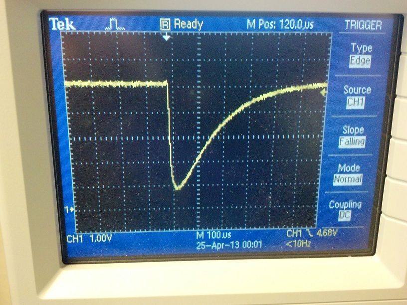
How about making a circuit that will quickly raise the voltage, and then slowly decay it?

If this is the input:

Code: Select all

___________________        _______________________________________________
                  |       /                                               
                  |      /
                  |     /
                  |    /
                  |   /
                  |  /
                  | /
                  |/
This would be the output:

Code: Select all

                   ____
                  |    \____
                  |         \____
                  |              \____
                  |                   \____
                  |                        \____
                  |                             \____
                  |                                  \____
                  |                                       \____
__________________|                                            \__________
I can try to draw up an example schematic.
Matt
http://mattallen37.wordpress.com/

I'm all for gun control... that's why I use both hands when shooting ;)
mattallen37
Posts: 1818
Joined: 02 Oct 2010, 02:19
Location: Michigan USA
Contact:

Re: NXT Geiger Counter

Post by mattallen37 »

There is currently no way (that I know of) to upload an image file directly (the forums won't accept the image file extensions), so I zipped a .jpg and uploaded that.
example short pulse - slow decay.zip
(19.01 KiB) Downloaded 738 times
I didn't test the circuit, I just assume that I got it right. The output will actually be normally high (like the input), and then get pulled low for some time when it gets a low pulse.

The output should look something like this:

Code: Select all

___________________                                             __________
                  |                                        ____/
                  |                                   ____/
                  |                              ____/
                  |                         ____/
                  |                    ____/
                  |               ____/
                  |          ____/
                  |     ____/
                  |____/
Do not add R3, as the NXT already has a pullup resistor on it's analog line.

I just assumed your output (that will connect to the input of this circuit) can sink current, because it will need to for this circuit to work (let me know if it can't, and I should be able to redesign it to work).

R1 will determine how much current can pass through T2, and into C1 (how fast C1 can charge).

C1 will determine how long the output pulse will last.

R2 will determine how long it takes to discharge C1, so it will also affect how long the output will last.

Like I said before, I didn't test the circuit, I am only assuming it will work.
Matt
http://mattallen37.wordpress.com/

I'm all for gun control... that's why I use both hands when shooting ;)
circuitmage
Posts: 68
Joined: 14 Dec 2012, 17:56
Location: Austin, TX

Re: NXT Geiger Counter

Post by circuitmage »

Thanks for fast reply.

Cannot pull up jpg yet...work puter having issues....but will get to it asap. I was thinking about a one shot or other gate to slow pulse hit down, but whatever works best.

So, what are the min pulse widths for RCX and NXT detection? I know from building powered RCX sensors that the power cycle time is 3ms and the read time is 0.1ms, but what about passive sensors? I was hoping for a nice speedy sense capability on passive, but looks like 100us still too fast for RCX.

I used the sound sensor on the NXT and it seems to have no problem picking up these hits, I believe the pulse is still about 100us on the geiger speaker.
mattallen37
Posts: 1818
Joined: 02 Oct 2010, 02:19
Location: Michigan USA
Contact:

Re: NXT Geiger Counter

Post by mattallen37 »

The NXT samples the analog lines at 300 (or 333?) Hz, so once every 3 1/3 or 3 ms. I don't remember what speed the RCX samples, but I think I remember hearing it's the same.

The circuit I designed is just a very basic version. If you need different characteristics (more sensitive, inverted voltage on input or output, less current load on the signal source, etc.), the circuit can be modified to meet almost any requirement.
Matt
http://mattallen37.wordpress.com/

I'm all for gun control... that's why I use both hands when shooting ;)
circuitmage
Posts: 68
Joined: 14 Dec 2012, 17:56
Location: Austin, TX

Re: NXT Geiger Counter

Post by circuitmage »

Ok, so basically a gated R-C.

That should do it. Will need to play with it abit, but the general concept should work.
I will need to try some things and update. I will probably shoot for a 5 or 10 ms pulse.

Also, I did find some stuff to confirm the sampling rates of the RCX and NXT. For some reason, I was thinking the NXT would be faster.

Just to be clear, my captured waveforms are from the transistor side of an opto with it's diode side in place of the geiger counter led. It really cleaned up the Geiger Counter side of the pulsing alot and led to a nice smooth signal as shown. The signals on the geiger counter board are very noisy. The LED is normally being banged by the HF pulses to the tube. Since they are AC coupled to the speaker and the LED, both are not very nice to look at.
I added a 1K resistor in series with the RCX wire (per passive touch sensor method) to the opto transistor. The waveform reflects the 5V to 0.45V drop nicely. However, I did check an old touch sensor and found it at 400 Ohms...and lots of variation on these on the web that people have reported (old grey type).
circuitmage
Posts: 68
Joined: 14 Dec 2012, 17:56
Location: Austin, TX

Re: NXT Geiger Counter

Post by circuitmage »

Update:

Almost there! After a couple days of thinking (ouch!) here is what I decided to try;

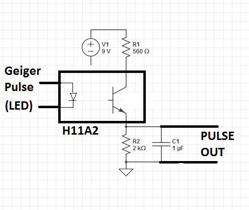
Image


To clarify, the Geiger LED can be substituted by the opto, which gives you a nice clean pulse. I don't need to invert the signal, but I do need to extend it. The critical issues here seem to be, getting the VDR to my 5V level (which is dependent on the R1 C1 charge rate), and getting an discharge constant that suffices (R2 C1).


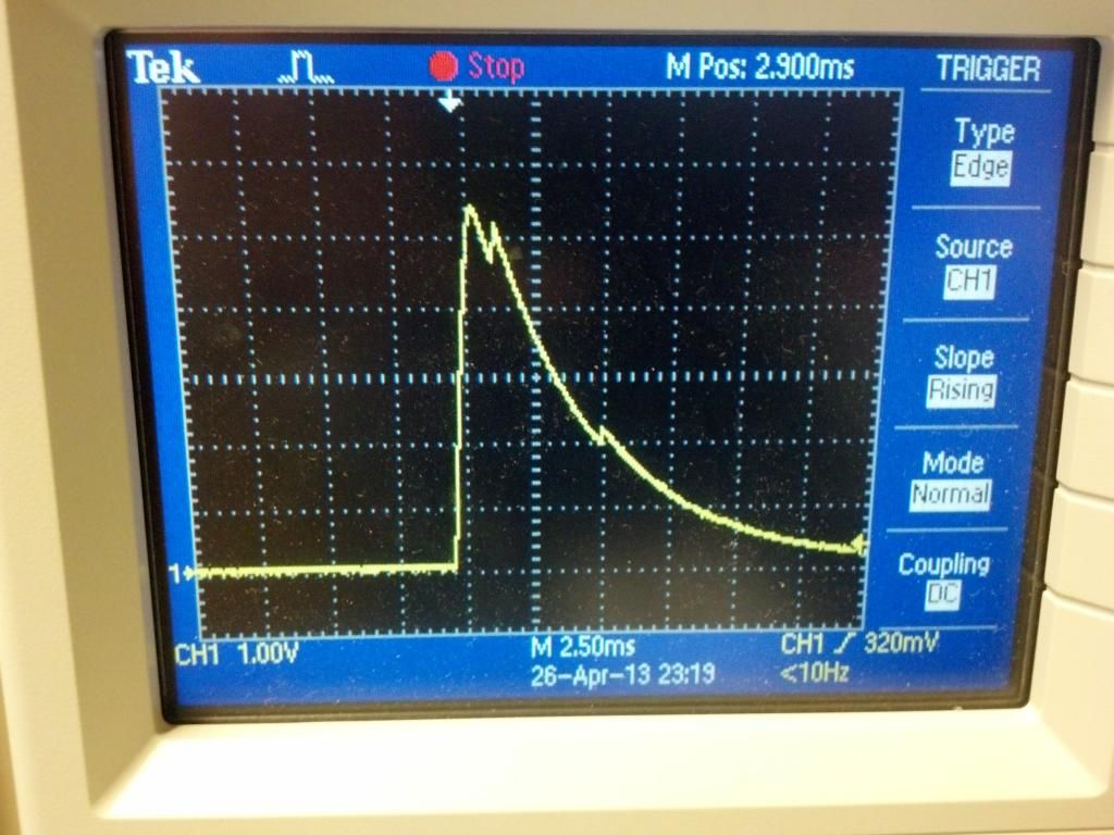
After a dozen or so attempts, this is where I am (Insufficient charge and insufficient discharge right now);

Image

I assume I will need 3.5V for at least 3ms. I would like 5V for 5 ms, but we will see....


Edit: Looking at this again....looks very clear cut. A simple charge pump and discharge is all, with the RC time constants the only concern. R1 C1 form the charge pump, R2 C1 is the discharge time. Looks like I just need to optimize my values.
circuitmage
Posts: 68
Joined: 14 Dec 2012, 17:56
Location: Austin, TX

Re: NXT Geiger Counter

Post by circuitmage »

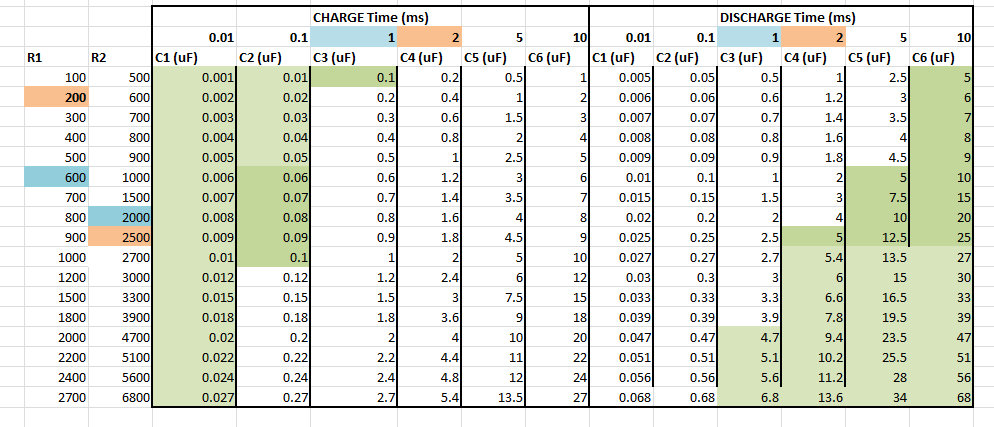
Ok, so what I have been looking at looks pretty close to t=RC, so here it is. I want to have my cake and eat it too;

Image


The Blue and Orange are values that looked good at 9V, but I now realize that it was not charging fully.
Green values are where I would like to be. I'm thinking if I drop Vcc to 5V and go with R1=100, R2=4700, C1=1uF then that should be close.

R1 will be underrated , but for only a 100us pulse....I'm thinking it will be ok. :shock:

I will probably need to tweak those values, but we will see.
Post Reply

Who is online

Users browsing this forum: No registered users and 2 guests