Page 1 of 1

NXT cable tester

Posted: 27 Mar 2012, 16:07
by h-g-t
I was looking at this http://www.rjmcnamara.com/2011/05/nxt-cable-checker/ with a view to modifying my network cable tester.

It occurred to me that removing the existing sockets seemed like a lot of work and would prevent me from using it with conventional cables unless I installed the LEGO sockets in parallel with the existing ones, possibly glued onto the outside of the cases.

So I wondered, why not build my own?

Not an electrician but it seemed that the sockets, 6 LEDS with resistors and a bit of scrap Veroboard should suffice.

I came up with this rough diagram and would appreciate any advice from the experts on mistakes I have made before starting work.
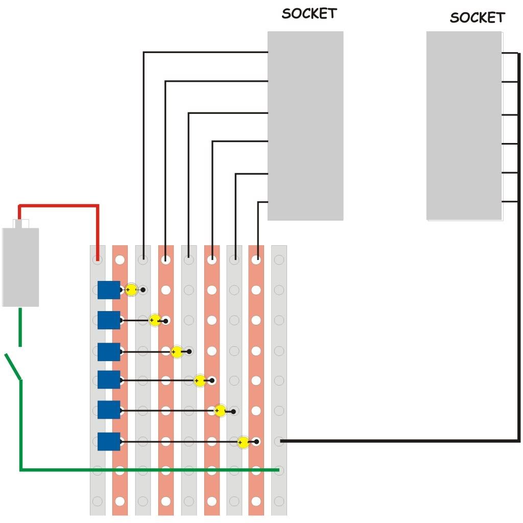
Image

Sorry about the size!

Re: NXT cable tester

Posted: 27 Mar 2012, 17:08
by mattallen37
You're diagram looks pretty good, but with one significant mistake. You connect the anode of all LEDs together, and then put all resistors in parallel, connecting to the + supply. Give me a bit, and I'll draw up the "proper" schematic for you.

Just about a week ago I made an NXT program to test cables. It requires one NXT, and one physically-free motor.

When you're running it, it will instantly (within a few ms) start beeping if wires 3, 4, 5, or 6 get dis-connected. If wires 1 or 2 get disconnected, the motor will immediately begin to float, and once it slows down, the NXT will detect it and start beeping (could take a second or so).

It does not determine which conductor is shorting.
Cable tester.nxc
(996 Bytes) Downloaded 327 times

Re: NXT cable tester

Posted: 27 Mar 2012, 17:09
by inxt-generation
Well I'm not an expert, per se, but I think that that should work.

EDIT: Gah! Matt beat me to it! I didn't notice the dots connecting all the resistors together before.

Re: NXT cable tester

Posted: 27 Mar 2012, 17:23
by mattallen37
Here is the schematic (ExpressSCH version), and a JPEG image of it.
NXT Cable tester.zip
(35.04 KiB) Downloaded 356 times

Re: NXT cable tester

Posted: 27 Mar 2012, 20:08
by mcsummation
For folks that don't want to build their own, Mindsensors sells one - http://www.mindsensors.com/index.php?mo ... tion=50:50.

Re: NXT cable tester

Posted: 27 Mar 2012, 22:14
by h-g-t
Well, I said it was a rough sketch, but it was even rougher than I thought!

The idea was that the left strip of Veroboard carried the positive power bus, and the leds with their resistors were powered off that - the apparent connections to the second strip were meant to be the connections to the resistors, not the Veroboard.

Thanks for all the replies.