Experimental Gyro Compass (LeJOS)

Discussion specific to NXT-G, NXC, NBC, RobotC, Lejos, and more.
aswin0
Posts: 201
Joined: 29 Sep 2010, 06:58

Re: Experimental Gyro Compass (LeJOS)

Post by aswin0 »

Hi,

It is my believe that errors due to sensors characteristics have far more effect on the integral than the integration method used. So, if you want to increase the quality of your integral (the heading) it is wise to concentrate on the sensor first. Even then there are some different aspects to keep into account. Most important is the quality of the offset. This is influenced by sample size, temperature and voltage (or changes in voltage). Xander already pointed out my blog, one of the posts deals with exactly this subject and provide methods to improve the offset. Second is linearity. We all assume that a change of 1 unit corresponds to a increase (or decrease) in rate of rotation of 1 degree. But this might not be the exactly true over the full range of the sensor. Third is noise. We assume this is normally distributed, so noise cancels itself out in the long run. But is it normally distributed? It could well be log normal, and then noise wouldn't cancel itself out.

There is one more thing that should be taken into account if you want the best heading using a gyro sensor. This is the rotational speed of the earth. This can add an extra 0.15 degrees a minute to the integral! :o

But, to be serious again, you should always keep your goals in mind. In most cases there is no need to try to go for the best possible value. Our robots don´t have to be able to home in on Saddam Housseins toilet.
My blog: nxttime.wordpress.com
kvols
Posts: 29
Joined: 14 Oct 2010, 22:09

Re: Experimental Gyro Compass (LeJOS)

Post by kvols »

Thanks, Andy and Aswin!

Aswin, I agree very much on your points regarding the integration method and offset value, and I have found a few issues in my program: The sensor was heavily biased by a default values in the LeJOS driver class. Eliminating that bias, and working on raw sensor values instead helped a great deal!

I read your blog, and I agree that the battery voltage and temperature has a great impact on the sensor readings. As you point out, I believe that taking the battery voltage into account can greatly improve the integration when the sensor is moving. (I looked at you Kalman filter code, and I simply don't get it. It's far beyond me how to obtain the values and filter out the sensor noise... :? Doesn't the Kalman filter normally use matrices and vector arithmetic to do the calculations?)

The integration itself appears to be quite accurate, and it appears to even out the filter noise, as long as the offset is correct. I'm really surprised about the accuracy of this little sensor!

I'll post a new release of the program, if anyone is interested...

Povl

And even though we do not intend to use the LEGO brick for missile guidance, the sensors and computer is probably more powerful than the stuff used on board the Apollo rockets when NASA went to the moon... ;)
kvols
Posts: 29
Joined: 14 Oct 2010, 22:09

Re: Experimental Gyro Compass (LeJOS)

Post by kvols »

gloomyandy wrote:You may want to try using a sample rate of 4ms rather than 5ms.
It appears that the sampling rate doesn't affect the accuracy too much. Even at 50 ms (20 samples/s), I still get pretty accurate turn ratios. The real difference is how fast I can change rotation speed. At 50 ms intervals, I have to accelerate slowly, whereas at 3 ms intervals I can change directions pretty fast, and still get accurate readings.

As I see it, the real source of the inaccuracy is by far the offset, as Aswin also points out. My main problem is that the offset fluctuates quite a lot. My simple method of trying to find the offset when I detect the sensor is motionless makes the presumed offset unstable. I have tried several ways of averaging out the noise, but the fluctuation continues to be a problem - and I haven't even added the motors yet! My next move is to stabilize the fluctuation by measuring the battery voltage, and trying to add that to the model, as Aswin suggests on his blog. It might work... I'll keep you posted!

Kindly,
Povl
gloomyandy
Posts: 323
Joined: 29 Sep 2010, 05:03

Re: Experimental Gyro Compass (LeJOS)

Post by gloomyandy »

The sample interval can be important it all depends on how you are using the sensor. Using midpoint integration basically assumes that the angular acceleration is constant over the sample period. The longer the sample period the less likely this is to be true. I would not use a sample period les than 4ms if you do so you will start to run into problems with getting the same reading multiple times. Take a look at this graph
Image
This uses a sample rate of 1ms. You can clearly see how with an analogue source (via he ATMega), the data is repeated in 4 and 2 groups (this is down to the way the data is sampled and made available)....

As to the offset, the best way to get rid of it,is to really understand it. I would run a series of tests graphing the results. Sample the sensor at rest, over a period of time, then do the same thing again as the battery drops, and then again with motors running (which may give different results, due to noise on the power lines from the motors). I did some of this and found that I saw the offset change a fair bit when you first start to use the device (due I think to self heating), and then change a little later due to voltage drop (though I didn't get as close a correlation to this as aswin did). It may be that particular sensors are different , or we may have had different battery setups... The more data you have the easier it is to work out what is going on...

Have fun

Andy
HaWe
Posts: 2500
Joined: 04 Nov 2014, 19:00

Re: Experimental Gyro Compass (LeJOS)

Post by HaWe »

I really doubt that it might be possible to erase the gyro reading errors (mainly based on drifting offsets) out of "itself" or by measuring the voltage or through the observance of motor running states (except maybe when using an empirical approach like self training neural feed-back nets, e.g. like Elman nets, or huge brick-, motor-, and battery-specific look-up tables).

In my mathematical understanding it's only possible by correction of other simultaneous measurements (compass, accelerometer, odometry) and by the use of a non-linear filter.
With this approach you don't correct neither the gyro reading nor the gyro offset but the weight of the result (e.g. the current heading) among other results from the perspective of it's probability.
(Understandable what I want to express?)
aswin0
Posts: 201
Joined: 29 Sep 2010, 06:58

Re: Experimental Gyro Compass (LeJOS)

Post by aswin0 »

doc-helmut wrote:I really doubt that it might be possible to erase the gyro reading errors (mainly based on drifting offsets) out of "itself" or by measuring the voltage or through the observance of motor running states.
It are not errors that are corrected here. And they are not corrected by themselves. There is the hypotheses that there is a relation between offset of the gyro is and the voltage the NXT runs on. This hypotheses was tested* by me and found to be true. (the test might not meet scientific criteria) I found a linear correlation between the battery voltage level and the offset.
doc-helmut wrote:In my mathematical understanding it's only possible by correction of other simultaneous measurements
This is exactly what I propose to do. Every time you read a raw gyro value you can also read the battery level of the NXT. Knowing the relation between battery level and offset value you can calculate the offset value at the time of the reading. This offset should then be used to correct the raw reading (instead of a static offset).

To conclude. It is no error that is corrected this way. It is just a more precise way of offset correction. It might make you happy to know that there are still errors in the end result.

* Some words about the test. I used a stationary NXT with a Gyro and two (port A and C) free running motors attached. During 4 minutes samples were taken of the gyro, motor power and battery level. A sample was taken every 5 mSec. I ended up with 34649 data points (some points were lost due to blue tooth). During this time different levels of (uncontrolled) motor power were applied to both of the motors. The motor power levels ranged from -100 to 100 in steps of 10. The plot below shows the average voltage versus the average offset for each of the power levels applied to the motors. So each point of the graph is the result of about 3500 measurements.
Image
My blog: nxttime.wordpress.com
HaWe
Posts: 2500
Joined: 04 Nov 2014, 19:00

Re: Experimental Gyro Compass (LeJOS)

Post by HaWe »

with error I meant offset drift error plus angle speed reading error.
To minimize the offset drift error by it's dependency from the battery voltage is surely a good start.
Is there only 1 unit drift at all to observe (594,5 - 595,5)? Or what is the maximum offset drift that can be observed over the whole run time and over all different battery levels?
kvols
Posts: 29
Joined: 14 Oct 2010, 22:09

Re: Experimental Gyro Compass (LeJOS)

Post by kvols »

I just did some tests myself, and I ended up with something similar to Aswin.

Test method:

I created a small statistics module:

Code: Select all

package com.kvols.stat;

import static java.lang.Math.sqrt;

public class Stat {
	int n;
	double sumX, sumY, sumXY, sumXX, sumYY;

	public void add(double x, double y) {
		n++;
		sumX += x;
		sumY += y;
		sumXY += x * y;
		sumXX += x * x;
		sumYY += y * y;
	}

	double getMean() {
		return sumX / n;
	}

	double standardDeviation() {
		return Math.sqrt((sumXX - sumX * sumX / n) / (n - 1));
	}

	public int getN() {
		return n;
	}

	public double getSumX() {
		return sumX;
	}

	public double getSumXX() {
		return sumXX;
	}

	public double getSumXY() {
		return sumXY;
	}

	public double getSumY() {
		return sumY;
	}
	
	public double getSumYY() {
		return sumYY;
	}

	public double getBeta() {
		return (sumXY/n - sumX * sumY/(n*n))
				/ ((sumXX / n - (sumX * sumX / (n * n))));
	}

	public double getAlpha() {
		return (sumY - getBeta() * sumX) / n;
	}

	public double getCorrelation() {
		return (n * sumXY - sumX * sumY)
				/ (sqrt(n * sumXX - sumX * sumX) * sqrt(n * sumYY - sumY * sumY));
	}

	@Override
	public String toString() {
		if(n<2)
			return "Empty stats";
		return "N=" + n + "\nb:"+(float)getBeta()+"\na:"+(float)getAlpha()+"\nC:"+(float)getCorrelation();
	}
}
The module correctness was tested with a JUnit test case:

Code: Select all

package com.kvols.stat;

import org.junit.Test;

import static org.junit.Assert.*;

public class StatTest {

	@Test
	public void testAddMethod() {
		Stat stat = new Stat();
		stat.add(1, 2);
		stat.add(2, 3);
		stat.add(3, 4);
		assertEquals("N", 3, stat.getN());
		assertEquals("sum x", 6, stat.getSumX(), 1e-12);
		assertEquals("sum y", 9, stat.getSumY(), 1e-12);
		assertEquals("sum x²", 14, stat.getSumXX(), 1e-12);
		assertEquals("sum xy", 20, stat.getSumXY(), 1e-12);
		assertEquals("sum y²", 29, stat.getSumYY(), 1e-12);
		System.out.println(stat);
	}

	@Test
	public void testCalculations() {
		Stat stat= new Stat();
		stat.add(5,3);
		stat.add(8,2);
		stat.add(6,9);
		stat.add(5,8);
		stat.add(3,4);
		stat.add(9,2);
		assertEquals("mean", 6, stat.getMean(), 1e-12);
		assertEquals("std.dev", 2.19089023002, stat.standardDeviation(), 1e-11);
		assertEquals("correlation", -.385704038913, stat.getCorrelation(), 1e-11);
		assertEquals("beta", -.541666666667, stat.getBeta(), 1e-11);
		assertEquals("alpha", 7.91666666667, stat.getAlpha(), 1e-11);
	}
}
The numbers for the test case (alpha, beta, correlation) was taken from my trusted HP50G calculator, and it matches.

I then created a small program for the LEGO brick to take some samples:

Code: Select all

import lejos.nxt.ADSensorPort;
import lejos.nxt.Battery;
import lejos.nxt.Button;
import lejos.nxt.LCD;
import lejos.nxt.SensorPort;

import com.kvols.stat.Stat;

public class GVSampler {
	public static void main(String[] args) throws InterruptedException {
		Stat stat= new Stat();
		ADSensorPort gyroPort= SensorPort.S1;
		gyroPort.setType(SensorPort.POWER_9V);
		
		for(;;) {
			LCD.clear();
			LCD.drawString(stat.toString(), 0, 0);
			int key= Button.readButtons();
			while(key == 0) {
				LCD.drawString("Gyro:"+gyroPort.readValue(), 0, 6);
				LCD.drawString("Batt:"+Battery.getVoltageMilliVolt(), 0, 7);
				Thread.sleep(50);
				key= Button.readButtons();
			}
			if(key==Button.ID_ENTER) {
				LCD.clear();
				LCD.drawString("Sampling...", 0, 3);
				for(int i=0; i<100; i++) {
					double batt= Battery.getVoltage();
					double gyro= gyroPort.readValue();
					batt= (Battery.getVoltage()+batt)/2;
					stat.add(batt, gyro);
					Thread.sleep(10);
				}
			}
			if(key==Button.ID_ESCAPE) break;
		}
	}
}
The brick was then attached to a DC power supply, and 20 iterations of 100 samples was taken from approx. 5.5V to 9.5V.

The result is quite similar to the results from Aswin:
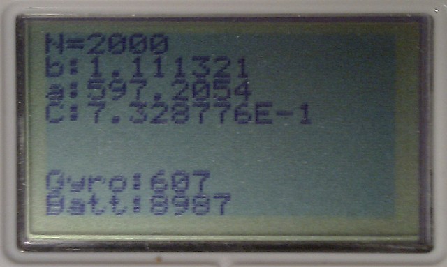
Battery/Gyro offset correlation
BattGyroCorrelation.jpg (52.12 KiB) Viewed 9843 times
For my sensor at this temperature, the approximate sensor offset would be:

Code: Select all

offset= 597.2054f + Battery.getVoltage() * 1.111321f
The correlation of 0.733 does indicate that there are other factors at stake here, eg. sensor noise, battery sensor noise. But still: It's probably a much better way of eliminating at least some of the sensor noise and get a bit more predictive results!

I'll keep you posted when I have a new version with the battery voltage taken into account!


Povl
gloomyandy
Posts: 323
Joined: 29 Sep 2010, 05:03

Re: Experimental Gyro Compass (LeJOS)

Post by gloomyandy »

Hi Aswin/Kvols/Folks,
out of interest did you try running your test over the same period with no change in the battery voltage (so using a constant supply)? Did you see any drift then? I would be surprised if there is none, which means that we have some other drift element to take into account, not sure how big this value is and if it is possible to model it based on time?
aswin0
Posts: 201
Joined: 29 Sep 2010, 06:58

Re: Experimental Gyro Compass (LeJOS)

Post by aswin0 »

gloomyandy wrote:Hi Aswin/Kvols/Folks,
out of interest did you try running your test over the same period with no change in the battery voltage (so using a constant supply)? Did you see any drift then? I would be surprised if there is none, which means that we have some other drift element to take into account, not sure how big this value is and if it is possible to model it based on time?
I did this test some time ago but I don't have the results anymore. I remember the offset dropping relatively fast in the first measurements and then slower and slower, like moving to an asymptote. However, I couldn't determine for sure If there really was an asymptote as the total drop was in the same range as the sensor noise. My conclusion from this test was that I should discard the first 100 readings (having a 4 msec refresh rate).

Hitechnic published some code for a balancing robot that uses their gyro. The offset determination algorithm in this code coast the motors before calculating the offset. Also the program only accepts an offset if the difference between the smallest and largest value in the sample is 1 or less. Otherwise rejects the offset and tries again. This is another way of dealing with offset settling.
My blog: nxttime.wordpress.com
Post Reply

Who is online

Users browsing this forum: No registered users and 49 guests