Question about output switch

News, rumors, and other broad discussion topics.
legrandtzar
Posts: 3
Joined: 22 Jan 2011, 17:07

Question about output switch

Post by legrandtzar »

I don't have the mindstorms set yet, so this may be a trivial question, but I am wondering wether it is possible or not to control an output switch from within the program. My idea is to control the shutter of my Canon SLR which uses a proprietary connector:

Image

Provided I make the cable between the N3 connector and the NXT, is it possible to program this simple switch? I have googled much but couldn't find much about output that wasn't related to motors. I found many "automatic light switch" bots but that relied on mechanical means to actually activate the switch.
mightor
Site Admin
Posts: 1079
Joined: 25 Sep 2010, 15:02
Location: Rotterdam, Netherlands
Contact:

Re: Question about output switch

Post by mightor »

Yes, it would be quite easy. Do you want both the shutter -and- focus?

- Xander
| My Blog: I'd Rather Be Building Robots (http://botbench.com)
| RobotC 3rd Party Driver Suite: (http://rdpartyrobotcdr.sourceforge.net)
| Some people, when confronted with a problem, think, "I know, I'll use threads,"
| and then two they hav erpoblesms. (@nedbat)
h-g-t
Posts: 552
Joined: 07 Jan 2011, 08:59
Location: Albania

Re: Question about output switch

Post by h-g-t »

I have used this arrangement :-
Lego Relay 02.jpg
(79.88 KiB) Downloaded 72 times
Use onfwd command to select one relay or onrev for the other followed by wait then off to stop the current and release the relay (non-latching of course).

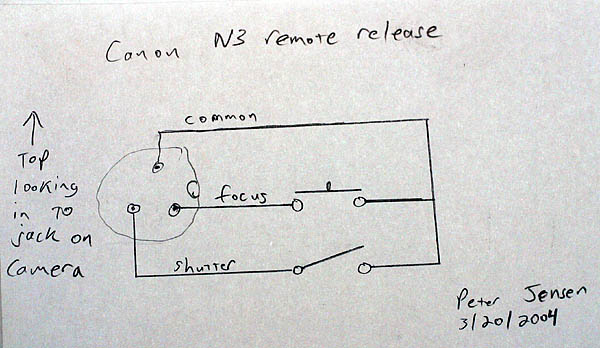
Bit of a guess as to the wait period for focusing since you don't know how long the camera will take. I am using 2 seconds at the moment. I allow 0.25 seconds for the shutter and that seems to work (so far!).

The relay voltage should be between 3 & 6 v imho since a 9v relay might not be reliable once the battery runs down.

You can use the batterylevel command in NXC or Guy Viv's NXT-G battery level block to find the actual voltage at any time. Then factor it down to get the motor power setting by 100*relay voltage/actual voltage. I reckon there will be a voltage drop of about 0.7v across the diodes so set the relay voltage at 6.7v for my 6v relays.

Any single pole non-latching relay should work but I have read that reed relays can affect each other if too close so I avoided these.

The remote cable I bought had no resistor in it, just a simple switch but I added one just to be on the safe side.

There is a ready-made version available at http://www.techno-stuff.com/relay.htm

The code I use is :-

focus_power = 100*focus_volts/BatteryLevel(); // Factor down voltage
shoot_power = 100*shoot_volts/BatteryLevel(); // Factor down voltage

if (focus == true) // Skip if auto focus not used
{
Wait (1000); // Wait for vibrations to cease
OnRev (OUT_C, focus_power); // Focus relay on Port C
Wait (focus_time); // Keep relay energised
Off(OUT_C); // Switch relay off
}

if (mirror == true) // Skip if mirror lock not used
{
OnFwd (OUT_C, shoot_power); // Mirror up - shoot relay Port C
Wait (shoot_time); // Keep relay energised
Off(OUT_C); // Switch relay off
}

Wait (2000); // Wait for vibrations to cease
OnFwd (OUT_C, shoot_power); // Shoot & drop mirror - relay Port C
Wait (shoot_time); // Keep relay energised
Off(OUT_C); // Switch relay off
Wait (2000);
Last edited by h-g-t on 22 Jan 2011, 20:05, edited 1 time in total.
A sophistical rhetorician, inebriated with the exuberance of his own verbosity, and gifted with an egotistical imagination that can at all times command an interminable and inconsistent series of arguments to malign an opponent and to glorify himself.
legrandtzar
Posts: 3
Joined: 22 Jan 2011, 17:07

Re: Question about output switch

Post by legrandtzar »

Thank you for your very fast and thorough answer. My intention was at least to have shutter control, but focus can of course be useful.

So indeed there is no native way to do this with just the starter kit. I had seen the relay block you mentionned, but it seems a bit pricey (+s&h), so I guess I'd rather assemble your solution myself. Did you use the ready made relay, and if not, could you give me a hint as to which components you actually used?
h-g-t
Posts: 552
Joined: 07 Jan 2011, 08:59
Location: Albania

Re: Question about output switch

Post by h-g-t »

Basically, whatever was cheapest on ebay!

Bought a pack of 5 SRD-06V-DC-SL-C spco relays for about £5 - £6 and there are similar units on there at the moment for about the same price. There is no reason to use identical relays for both halves of the circuit as long as you remember to factor the power going to each relay. For instance, if you have a 3v and a 4.5v relay already you can use them. The code I showed earlier has different variables for focus_power and shoot_power to accommodate this situation.

I splashed out on the diodes, going for a pack of 50 1N4004s when 1N4001s would have done but, hey, you only live once!

The 3.5mm stereo audio socket I had already and I initially adapted the cable from the remote release I bought (ebay of course) but now use a ready-made 3.5mm - 2.5mm stereo cable bought for £1.99. Looks better and has a 90 degree bend on the plug at the camera end. Push buttons were just standard push-to-make cheapos. Not really necessary but it means you can use it as a standard remote if you want. The original remote I bought had a straight metal to metal connection but I added a resistor just to limit the current from the camera.

For the first one I butchered a plastic case for holding 8 AA batteries. When I knew it worked I made a new one using a Vero board and for this I modified a plastic box which used to hold a pair of cuff links. As a Scot, I prefer to use what is lying about rather than buying something new. Wouldn't bother with the pcb next time though, just wiring it and using heat-shrink tubing to hold it all together works fine.

Both circuits are identical, you just connect the white wire to relay positive on one side and the black wire to relay positive on the other. If you don't want focus then just build one side.

The socket is wired with the shutter relay connected to the tip of the plug on the cable, the focus relay to the middle band and the common to the main body of the plug. I use a Canon 400D so it should be the same for yours. It is easy enough to test, plug a cable in and short out the elements on the plug at the other end to see what happens. I used a socket because I have a Fuji with a different type of connector at the camera and need to switch cables. If you are only going to use one camera you can solder your cable straight onto the relays.

The cable to the brick is a short NXT cable cut in half. Extensions were connected to the black and white wires and led to the circuit in the case. The other end goes into one of the motor sockets on the top of the brick. The unused wires were cut to different lengths and sealed with heat-shrink tubing to avoid the possibilities of shorts which might damage the brick. The b & w wires originally went to the motors and the current flows one way to drive the motors forward and the other for reverse. Voltage is varied to set the motor power and can be up to 9v, which is why you have to factor it to avoid burning out the relays.

Since this just uses a very simple command to run the motors, I don't see any reason why you could not operate this circuit with one of the old RXC units instead of an NXT. If I am wrong then no doubt I will be corrected very quickly!

Hope this helps.

PS - I noticed that the commercial product (which uses a very similar circuit) includes a 220 ohm resistor on the brick side of the circuit, presumably to limit the current being drawn from the brick. I did not consider that because the relays I bought only drew a small current and the diodes offer some resistance but it might be something to think about.
Last edited by h-g-t on 22 Jan 2011, 21:36, edited 1 time in total.
A sophistical rhetorician, inebriated with the exuberance of his own verbosity, and gifted with an egotistical imagination that can at all times command an interminable and inconsistent series of arguments to malign an opponent and to glorify himself.
legrandtzar
Posts: 3
Joined: 22 Jan 2011, 17:07

Re: Question about output switch

Post by legrandtzar »

thank you, this is very helpful. Actually, I have a canon 7d so the socket is different from an audio jack, it's a N3 connector. There are cheap chinese remote controls on ebay from which I could get the female connector. With your information, I think I can actually pull this off.
On a related matter, is it possible to use IR blocks to emulate canon IR wireless remote controls?
h-g-t
Posts: 552
Joined: 07 Jan 2011, 08:59
Location: Albania

Re: Question about output switch

Post by h-g-t »

Don't know about the IR stuff, you will need to wait for one of the experts. Seems likely that you might be better off with an RCX if you are going to try that since they use IR to communicate whereas the NXT uses usb and Bluetooth.

However ..... those IR remotes on ebay are so cheap that it might be worth buying one, pulling it apart and seeing if you can find a way to connect the relays in parallel with the buttons which operate the circuit. That is what I did to build this device.

I looked at the IR remotes to start with but the problem is that you have to find a way of fixing the remote to the front of the camera unless you know exactly where the camera is going to be pointing. In my case the remote was to be used with an automatic pano head so had to be capable of moving with the camera. It seemed much easier and more flexible to use the socket provided on the side of the camera.

Don't let me stop you though, you only learn by trying.
A sophistical rhetorician, inebriated with the exuberance of his own verbosity, and gifted with an egotistical imagination that can at all times command an interminable and inconsistent series of arguments to malign an opponent and to glorify himself.
nxtreme
Posts: 246
Joined: 29 Sep 2010, 03:53
Location: 192.168.1.2

Re: Question about output switch

Post by nxtreme »

h-g-t wrote:Don't know about the IR stuff, you will need to wait for one of the experts. Seems likely that you might be better off with an RCX if you are going to try that since they use IR to communicate whereas the NXT uses usb and Bluetooth.

However ..... those IR remotes on ebay are so cheap that it might be worth buying one, pulling it apart and seeing if you can find a way to connect the relays in parallel with the buttons which operate the circuit. That is what I did to build this device.
I'm by no means an expert but I do know a few things that might help. There are a few IR camera remote designs on Instructables, but in my thirty seconds of searching I couldn't find any for Canon cameras. However, I do agree with h-g-t here, stick to wired :).

Floydbloke has done some work with wired camera triggers. I think that this might be the easiest way to get something working fast as he uses the I2C bus (available on any NXT sensor port), a PCF8574 IC, and a 4066 IC to trigger the camera. I don't remember if it had the focus tied in as well, but that'd be easy to do and wouldn't require any more chips. Find his post here.
One King to rule them all, One King to find them,
One King to bring them all and in the darkness bind them
On Earth where Shadows lie.
h-g-t
Posts: 552
Joined: 07 Jan 2011, 08:59
Location: Albania

Re: Question about output switch

Post by h-g-t »

I'm not familiar with electronics but have rebuilt motorcycles so I went the mechanical route. Also, I was worried that if I tried anything electrical and it went wrong that stray voltages might fry the circuits in the camera.

That looks very interesting though but a bit more expensive by the time you add in boards,etc.

However, since I have already ordered a mini board (PCF8547) from futurlec to learn a little more about interfacing I might try it out. That will make it the sixth shutter release mechanism I have made for my pano head, I'm bound to get it right sometime!

PS - just bought 20 no 4066 for £1.99 from ebay so I can afford to fry a few whilst trying this out.
A sophistical rhetorician, inebriated with the exuberance of his own verbosity, and gifted with an egotistical imagination that can at all times command an interminable and inconsistent series of arguments to malign an opponent and to glorify himself.
nxtreme
Posts: 246
Joined: 29 Sep 2010, 03:53
Location: 192.168.1.2

Re: Question about output switch

Post by nxtreme »

Yes, I usually prefer to keep my more expensive electronics (camera, eTrex GPS, computer ect.) "un-connected to", minimizes risks. If your worried about frying something I've found that just posting the schematic here on the forums and asking peoples opinions will usually eliminate 90% of the problems that your circuit might have.

If your really wanting to create sensors or such for your NXT I recommend the Extreme NXT book by Michael Gasperi and Philo (as he's know around here :)). It can be had for under $6 US dollars shipped, if your living in the States or Canada. I got a digital version of the first edition and when the second came out I just had to have it. It's money well spent :).
One King to rule them all, One King to find them,
One King to bring them all and in the darkness bind them
On Earth where Shadows lie.
Post Reply

Who is online

Users browsing this forum: No registered users and 17 guests