I was looking at this http://www.rjmcnamara.com/2011/05/nxt-cable-checker/ with a view to modifying my network cable tester.
It occurred to me that removing the existing sockets seemed like a lot of work and would prevent me from using it with conventional cables unless I installed the LEGO sockets in parallel with the existing ones, possibly glued onto the outside of the cases.
So I wondered, why not build my own?
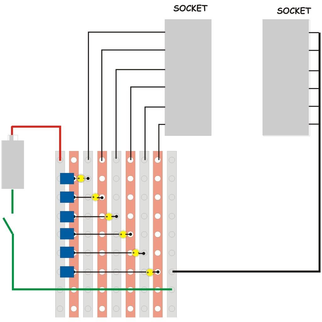
Not an electrician but it seemed that the sockets, 6 LEDS with resistors and a bit of scrap Veroboard should suffice.
I came up with this rough diagram and would appreciate any advice from the experts on mistakes I have made before starting work.
Sorry about the size!
NXT cable tester
NXT cable tester
A sophistical rhetorician, inebriated with the exuberance of his own verbosity, and gifted with an egotistical imagination that can at all times command an interminable and inconsistent series of arguments to malign an opponent and to glorify himself.
-
- Posts: 1818
- Joined: 02 Oct 2010, 02:19
- Location: Michigan USA
- Contact:
Re: NXT cable tester
You're diagram looks pretty good, but with one significant mistake. You connect the anode of all LEDs together, and then put all resistors in parallel, connecting to the + supply. Give me a bit, and I'll draw up the "proper" schematic for you.
Just about a week ago I made an NXT program to test cables. It requires one NXT, and one physically-free motor.
When you're running it, it will instantly (within a few ms) start beeping if wires 3, 4, 5, or 6 get dis-connected. If wires 1 or 2 get disconnected, the motor will immediately begin to float, and once it slows down, the NXT will detect it and start beeping (could take a second or so).
It does not determine which conductor is shorting.
Matt
http://mattallen37.wordpress.com/
I'm all for gun control... that's why I use both hands when shooting
http://mattallen37.wordpress.com/
I'm all for gun control... that's why I use both hands when shooting
-
- Posts: 290
- Joined: 03 Oct 2011, 00:06
- Location: Gallifrey
- Contact:
Re: NXT cable tester
Well I'm not an expert, per se, but I think that that should work.
EDIT: Gah! Matt beat me to it! I didn't notice the dots connecting all the resistors together before.
A.K.A. NeXT-Generation.
"A kingdom of heaven for RobotC now has recursion!"
-
- Posts: 1818
- Joined: 02 Oct 2010, 02:19
- Location: Michigan USA
- Contact:
Re: NXT cable tester
Here is the schematic (ExpressSCH version), and a JPEG image of it.
Matt
http://mattallen37.wordpress.com/
I'm all for gun control... that's why I use both hands when shooting
http://mattallen37.wordpress.com/
I'm all for gun control... that's why I use both hands when shooting
-
- Posts: 220
- Joined: 23 Jan 2012, 17:07
- Location: Round Rock, TX
Re: NXT cable tester
For folks that don't want to build their own, Mindsensors sells one - http://www.mindsensors.com/index.php?mo ... tion=50:50.
McSummation aka James
http://www.mcsummation.com/Mindstorms/
Re: NXT cable tester
Well, I said it was a rough sketch, but it was even rougher than I thought!
The idea was that the left strip of Veroboard carried the positive power bus, and the leds with their resistors were powered off that - the apparent connections to the second strip were meant to be the connections to the resistors, not the Veroboard.
Thanks for all the replies.
The idea was that the left strip of Veroboard carried the positive power bus, and the leds with their resistors were powered off that - the apparent connections to the second strip were meant to be the connections to the resistors, not the Veroboard.
Thanks for all the replies.
A sophistical rhetorician, inebriated with the exuberance of his own verbosity, and gifted with an egotistical imagination that can at all times command an interminable and inconsistent series of arguments to malign an opponent and to glorify himself.
Who is online
Users browsing this forum: No registered users and 4 guests